Topics for v2.x
Topics for v1.x
Creating your first scene
Welcome to the beginners tutorial. This will be a very basic overview of the editor and the various parts of it. During the walk though we will create a very simple scene that shows a spinning cube.
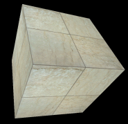
After going though this tutorial you will have scene that looks like this
Start the editor by going to the start menu->Programs->Plane9->Scene editor.
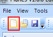
Create a new scene by either clicking on the File->New scene menu or on the blank paper icon.
A scene that have a few nodes already created for you should now show up. The inital scene has 3 nodes that are connected to one another. A scene is evaluated from left to right. So first the Clear1 node clears the screen then the RenderObject1 node renders a object.
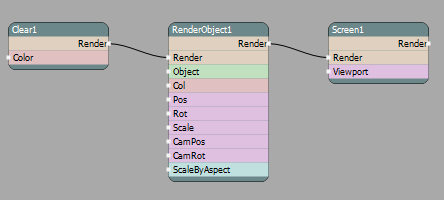
Currently nothing is shown in the render window since we haven't connected a object to render yet.
On the node that says RenderObject1 right click on the Object port that is on the left side on the node
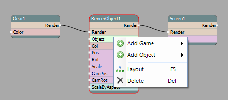
In context menu that showed up choose "Add object" and then "MeshObject". This will connect the RenderObject1 input port to the output port of the MeshObject1.
A mesh object combines a mesh that consists of vertices and polygons with a shader effect
On the newly created MeshObject1 right click on the Mesh input port to the left and select Add Mesh then Cube
Next we need to apply a shader to the object. On the MeshObject1 right click on the "Effect" to the right and choose "Add effect" and then "Shader". Now you should see a blob in the render window.
The default shader renders a simple blob by default.
So far the scene should look like this
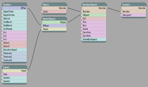
The blob we now see in the render window isn't the most exciting so lets make it a bit more interesting.
On the Shader1 node right click the Texture port and select "Add texture" then "FileTexture". This creates a file texture node. It will load in a texture from disk. By default a marble texture will be loaded.
Left click on the top of the the Shader1 node to select it. Scroll down to the bottom in the port that is called Shader in the Ports window. One line stars with two "/". Remove those. This line was commented out but tells the shader to use the texture we previously loaded and use the color from that texture. To make the shader more correct you can remove the bottom "return" statement. So the final Shader looks like this
struct PSInput
{
	float4 hpos : POSITION;
	float4 diffuse : COLOR0;
	float2 tex : TEXCOORD0;
};

PSInput VS_Program(VSInput vi)
{
	PSInput pi;
	pi.hpos		= mul( gWVP, float4(vi.pos.xyz, 1.0));
	pi.tex		= vi.tex;
	pi.diffuse	= vi.col*color1*color;
	return pi;
}

float4 PS_Program(PSInput pi) : COLOR
{
	float2 p = -1.0 + 2.0 * pi.tex;
	return tex2D(tex1, pi.tex)*pi.diffuse;
}
Lets bring our cube a bit closer so we can see the new texture better.
- Click on the RenderObject1 node. Currently the port named Cam Pos Z has a value of -10. Click with the left mouse button on the label that says "Cam Pos Z" and hold it down. Now move the mouse to the right and left. The value will change and you will see the object move closer and further away from you. You can make this change go faster or slower by holding down shift or ctrl. Alternatively you can just change the value directly by clicking the value box and write in a new value. Set the value to -2 to make the object nice and large.
Lets make the object rotate also so we can actually see that it is a cube.
- In the dag window right click on the port called Rot on the RenderObject1 node. "Select other" and "Vector".
This port converts the x,y,z value that a rotation consist of into its components so we can connect the components of the vector to other nodes individually
- On the newly created Vector1 node right click the "x" port and select "Add math" and "Rotator". The rotator node is used to just rotate a value. So it goes up to 360 (degrees) then wraps back to 0.
Now the object should start to rotate around the x axis but lets make it rotate around all 3.
Left click and hold the mouse button down on the port called RotY on the Rotator1 node. Drag it up to Vector1 port "y".
Left click and hold the mouse button down on the port called RotZ on the Rotator1 node. Drag it up to Vector1 port "z".
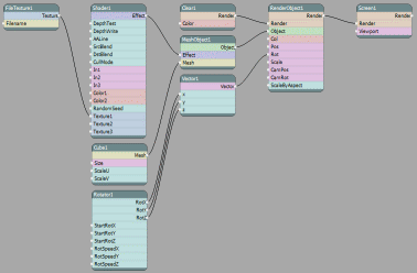
The complete scene should look like this
 Lets finish up so we can actually use this as our new screensaver.
Click on any gray area in the dag window. Now you will see the scenes properties where the port information previously was shown
Change the author and description as you want then under "Scene types" click in Standalone and Foreground since this scene should work for that. This scene isn't very exciting as standalone but its just so you can see it more easily in the configuration program.
Click "Ctrl+S" or go up to the file menu and choose save as. Write in a scene name like "MyFirstScene"
Now we are done in the editor so you can close it
- Start the configuration program by going to Start Menu->Programs->Plane9->Configure Plane9. Under the screensaver and music tabs you should see your scene. Select it and click "Preview scene" to see it.
You can download the complete scene
This concludes this tutorial. I hope this has sparked your interest to start to create your own scenes!
Things to try
- Change to another texture
- Change the texture repetitions (tip:ScaleU/ScaleV on the Cube1 node)
- Change the return shader statement we added before to
float4 PS_Program(PSInput pi) : COLOR
{
	float2 p = -1.0 + 2.0 * pi.tex;
	return tex2D(tex1, pi.tex+atan(p.y,p.x)*2+time/3.14)*pi.diffuse*length(p);
}